4.3 THRUST CHAMBER CONFIGURATION LAYOUT
After major thrust chamber operating parameters such as type of propellants, thrust level, chamber pressure, , and have been established from engine system requirements and performance calculations, one of the fundamental dimensions of the thrust chamber, the throat area , can be readily derived (eq. (1-33)). The throat area or throat diameter usually is the starting point of a thrust chamber configuration layout. The combustion chamber and nozzle section are commonly designed as an integral thrust chamber body. For light weight and ease of manufacture, thrust chambers will have the general shape of a pressure vessel with wall surfaces of rotation and smooth contours.
Combustion Chamber Volume
The combustion chamber serves as an envelope to retain the propellants for a sufficient period (stay time) to assure complete mixing and combustion before entering the nozzle. The volume of the combustion chamber thus has a definite effect on combustion efficiency. The theoretical required chamber volume is a function of the mass flow rate of the propellants and their average density, and of the stay time needed for efficient combustion. The relationship can be expressed by the following equation:
where:
A useful parameter, the characteristic length (commonly pronounced "L-star"), can be used to specify the propellant stay time in the combustion chamber. is defined as the ratio of chamber volume to nozzle throat area, and can be expressed by the following equation:
Since the value of is in nearly direct proportion to the product of and is essentially a function of . The effect of on in an experimental combustion chamber is shown in figure 4-7. The value increases with to an asymptotic maximum. Increasing beyond a certain point tends to decrease overall engine system performance because of the following: (1) Larger results in higher thrust chamber volume and weight. (2) Larger creates more surface area in need of cooling. (3) Larger increases friction losses at the chamber walls. In actual design practice, optimization analyses will determine the minimum possible combustion chamber consistent with efficient combustion.
Under a given set of operating conditions, such as type of propellants, mixture ratio, chamber pressure, injector design, and chamber geometry, the value of the minimum required can only be evaluated by actual firings of experimental thrust chambers. L* values of 15 to 120 inches for corresponding propellant stay-time values of 0.002-0.040 second have been used in various thrust chamber designs. Typical values for different propellants are given in table 4-1. With and minimum required established, the required combustion chamber volume can be calculated by equation (4-4).
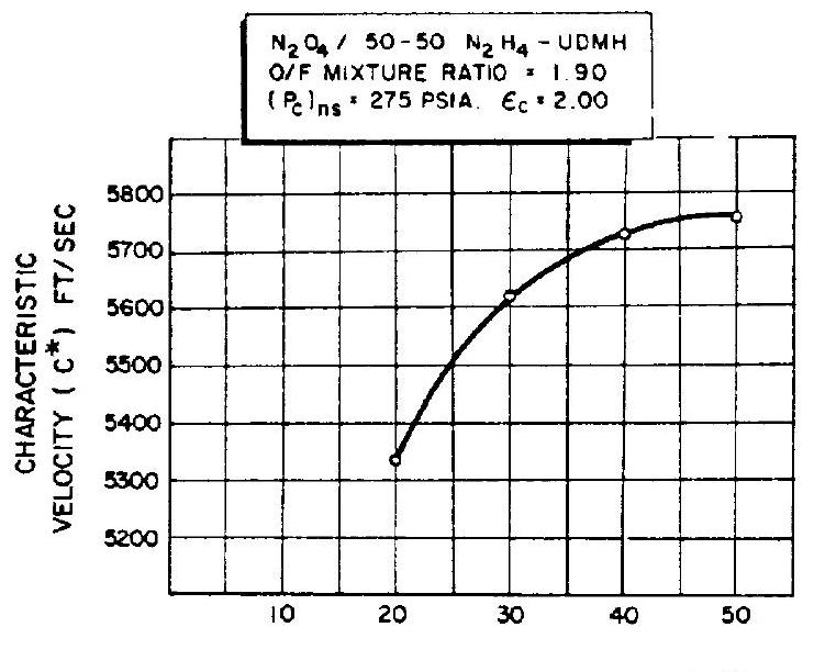 Figure 4-7.-Effect of on value of experimental thrust chamber.
Table 4-1.-Recommended Combustion Chamber Characteristic Length (L*) for Various Propellant Combinations
| Propellant combination | Combustion chamber characteristic length ( ), in. |
|---|---|
| Chlorine trifluoride/hydrazine-base fuel | 30-35 |
| Liquid fluorine/hydrazine | 24-28 |
| Liquid fluorine/liquid hydrogen ( injection) | 22-26 |
| Liquid fluorine/liquid hydrogen ( injection) | 25-30 |
| Hydrogen peroxide RP-1 (including catalyst bed) | 60-70 |
| Nitric acid/hydrazine-base fuel | 30-35 |
| Nitrogen tetroxide/hydrazine-base fuel | 30-35 |
| Liquid oxygen/ammonia | 30-40 |
| Liquid oxygen/liquid hydrogen ( injection) | 22-28 |
| Liquid oxygen/liquid hydrogen ( injection) | 30-40 |
| Liquid oxygen RP-1 | 40-50 |
Combustion Chamber Shape
As can be seen from equation (4-3), the stay time is independent ? the combustion chamber geometry. Theoretically, for a given required volume, the chamber can be of any shape. In actual design, however, the choice of the combustion chamber configuration is limited. In a long chamber with a small cross section, higher nonisentropic gas flow pressure losses will result as explained in chapter I. This approach also dictates a longer thrust chamber space envelope and imposes certain space limitation on the injector design to accommodate the necessary number of injector holes. With a short chamber of large cross section, the propellant atomization or vaporization zone occupies a relatively large portion of the chamber volume, while the mixing and combustion zone becomes too short for efficient combustion. Other factors, such as heat transfer, combustion stability, weight, and ease of manufacturing, are to be considered in determining the final combustion chamber configuration.
Three geometrical shapes which have been used in combustion chamber design are shown in figure 4-8. While the spherical and the nearspherical chambers were used in earlier European designs, the cylindrical chamber has been used most frequently in the United States.
The spherical or nearly-spherical chamber, as compared to the cylindrical one of the same volume, offers the advantage of less cooling surface and weight. A sphere has the smallest surface-to-volume ratio. For equal strength of material and chamber pressure, the structural walls of the spherical chamber are about half the thickness of the walls of a cylindrical chamber. However, the spherical chamber is more difficult to manufacture and has poorer performance under most circumstances. For these practical reasons, the design details of the cylindrical combustion chamber will be treated in this book. Several
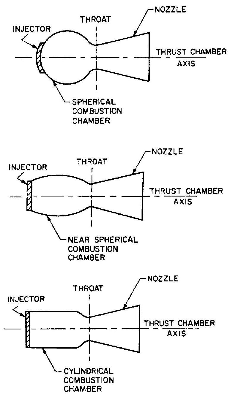 Figure 4-8.-Frequently used geometrical shapes for combustion chambers.
novel thrust chamber designs will also be discussed.
In the design layout of the cylindrical combustion chamber of a given and , the value of the contraction area ratio, ( ) can be optimized through careful studies of the following factors: (1) Combustion performance in conjunction with the injector design (2) Chamber gas flow pressure drop (3) Chamber wall cooling requirements (4) Combustion stability (5) Weight (6) Space envelope (7) Ease of manufacturing
For pressurized-gas propellant feed, lowthrust engine systems contraction area ratio values of 2 to 5 have been used. For most turbopump propellant feed, high thrust and high chamber pressure engine systems lower ratio values of 1.3 to 2.5 are employed. The reader is also referred to section 1.2 chapter I, "The Gas-flow Processes in the Combustion Chamber and the Nozzle."
The basic elements of a cylindrical combustion chamber are identified in figure 4-9. In design practice, it has been arbitrarily defined that the combustion chamber volume includes the space between injector face I-I and the nozzle throat plane II-II. The approximate value of the combustion chamber volume can be expressed by the following equation
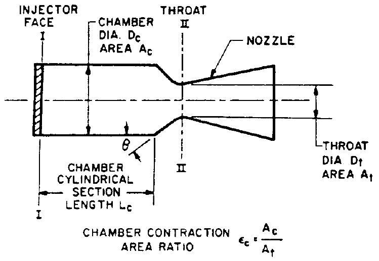 Figure 4-9.-Elements of basic cylindrical combustion chamber.
The total surface area of the combustion chamber walls excluding injector face can be approximated by the following expression:
Nozzle Expansion Area Ratio
It was learned earlier that with all other parameters fixed, in particular chamber pressure, there is only one optimum nozzle expansion area ratio for a given altitude or, more specifically, ambient pressure. Except for those systems which start in vacuum, ambient pressure will have to be considered. This is especially true for boosters which start at or near sea-level conditions.
It is the ultimate purpose of a rocket engine to lift vehicles to altitudes. Inherently, then, ambient pressure will not be a constant (except for high-altitude starts, as mentioned). It is, therefore, extremely important for the designer to know the trajectory of the vehicle to be propelled or, more specifically, its altitude-versus-time characteristics. With this information, the designer is in a position to make a first, optimizing selection of a nozzle expansion area ratio, for best results throughout the entire trajectory. As shown earlier, area ratio will be truly optimum for only one specific altitude. The optimization for ambient pressure then is essentially an averaging process.
Other considerations usually cause the designer to deviate from the "paper optimum" for the nozzle expansion area ratio. Some of the most common are: weight, size, ease of manufacturing, handling, and cooling (heat transfer) considerations.
Nozzle Shape
Most rocket nozzles are of the convergingdiverging De Laval type. Since the flow velocity of the gases in the converging section of rocket nozzle is relatively low, any smooth and wellrounded convergent nozzle section will have very low energy losses. By contrast, the contour of the diverging nozzle section is very important to performance, because of the very high flow velocities involved.
The selection of an optimum nozzle shape for a given expansion area ratio is generally influenced by the following design considerations and goals: (1) Uniform parallel axial gas flow at the nozzle exit for maximum momentum vector (2) Minimum separation and turbulence losses within the nozzle (3) Shortest possible nozzle length for minimum space envelope, weight, wall friction losses, and cooling requirements (4) Ease of manufacturing
In actual design practice, any abrupt change or discontinuity in the nozzle wall contour should be avoided to eliminate the possibility of shock waves or turbulence losses. Theoretically, the nozzle throat is simply the unique plane of minimum cross-section area. In practice, a wellrounded throat section is employed. Only at the nozzle exit plane is a sharp edge used because a rounded one would permit overexpansion and flow separation.
1. Conical Nozzle
In early rocket engine applications, the conical nozzle, which had proved satisfactory in most respects, was used almost exclusively. The advantages of a conical nozzle are ease of manufacturing and flexibility of converting an existing design to higher or lower expansion area ratios without major redesign of the nozzle contour.
The configuration of a typical conical nozzle is shown in figure 4-10. The nozzle throat section has the contour of a circular arc with a radius ranging from 0.5 to 1.5 times the throat radius . The half angle of the nozzle convergent cone section can range from to . The
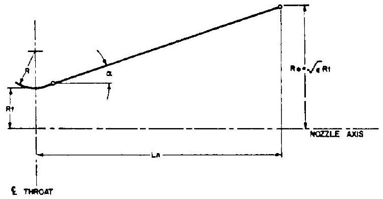 Figure 4-10.-Conical nozzle contour.
divergent cone half angle a varies from approximately to . The length of the conical nozzle section can be expressed by the equation
The conical nozzle with a divergent half angle has become almost a standard, as it is a good compromise on the basis of weight, length, and performance.
Since in a conical nozzle certain performance losses occur as a result of the nonaxial component of the exhaust gas velocity, a correction factor is applied for the calculation of the exit gas momentum. This factor or thrust efficiency is the ratio between the exit gas momentum of the conical nozzle and that of an ideal nozzle with uniformly parallel axial gas flow. The value of can be expressed by the following equation:
where half angle of the conical nozzle. For an ideal nozzle, would be unity. For a conical nozzle with and , the exit gas momentum or the exit velocity will be 98.3 percent of the ideal nozzle exit velocity calculated by equation (1-18). The value of the vacuum thrust coefficient of a nozzle is in direct proportion to the thrust generated by the nozzle, or to the nozzle exit gas velocity. Therefore, the theoretical vacuum thrust coefficient (neglecting friction and other flow losses) of a conical nozzle with half angle will be 98.3 percent of the ideal nozzle thrust coefficient calculated by equation (1-33a).
2. Bell Nozzle
For increased performance and shorter length, bell-shaped nozzles have been developed. This nozzle design employs a fast expansion or radial flow section in the initial divergent region, which then leads over to a uniform, axially directed flow at the nozzle exit. The wall contour is changed gradually enough so that oblique shocks will not form.
Figure 4-11 shows the contour of a bell nozzle. A circular arc of selected radius is
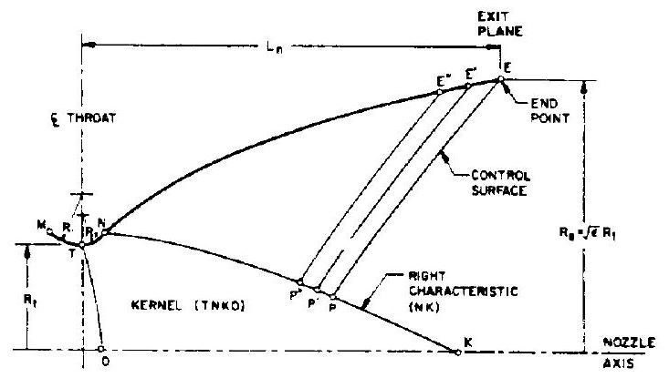 Figure 4-11.-Bell nozzle contour.
chosen for the nozzle contour MT upstream of the throat. Contour TNE is the diverging portion of the nozzle. The initial expansion occurs along contour TN; contour NE turns the flow over to a direction nearer to axial. For design convenience, the contour TN is also a circular arc, with a smaller radius .
For those familiar with compressible flow theories, it is noted that, using transonic flow analyses, a constant-Mach-number line TO can be defined at the throat. Given the flow condition along TO and the solid boundary TN, a kernel flow field TNKO can be generated by the method of characteristics developed in gas dynamics. The kernel of the rocket nozzle contour is defined as that portion of the supersonic flow field determined entirely by throat conditions. The last right characteristic line NK of kernel TNKO, and thus the location of the point N along contour TN, is to be determined by specific design criteria.
The location of the end point E along contour NE is defined by the given nozzle expansion area ratio and nozzle length (distance between throat and exit plane). Then the right characteristic line NK can be determined by satisfying the following conditions concurrently: (1) A control surface PE can be generated between the point E and a selected point P along the line NK (2) Mass flow across PE equals the mass flow across NP (3) Maximum thrust by the nozzle is attained.
By selecting points , etc., along line NK, a series of control surfaces , etc., can be generated to define points , etc., along the contour NE. Calculations for the nozzle contour can be effectively performed by a computer.
 FRACTIONAL NOZZLE LENGTH (Lp) BASED ON A HALF ANGLE CONICAL NOZZLE WITH ANY AREA RATIO
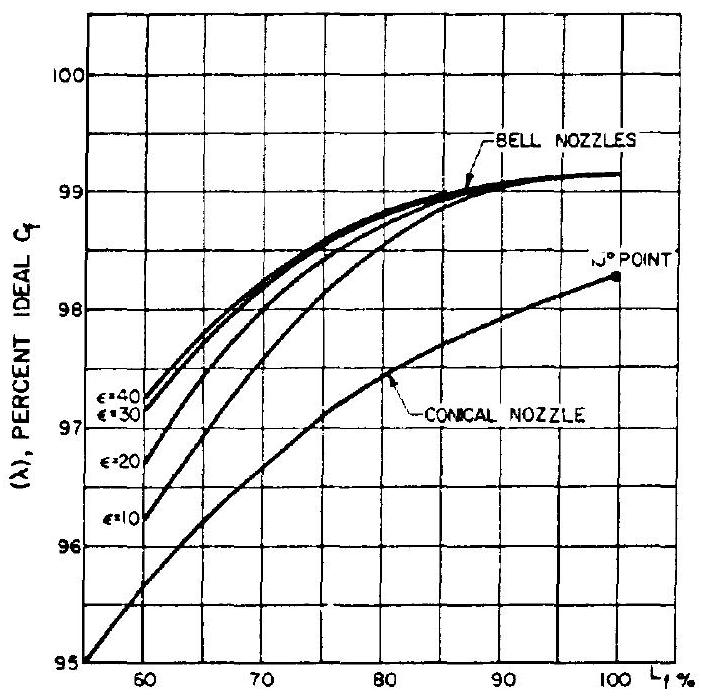
Figure 4-12.-Thrust efficiency versus bell nozzle length. (Shown for comparison: effect of shortening conical nozzle, increasing half angle.)
Commonly, an equivalent half-angle conical nozzle is used as a standard to specify bell nozzles. For instance, the length of an percent bell nozzle (distance between throat and exit plane) is 80 percent, or 0.8 of that of a half-angle conical nozzle having the same throat area, radius below the throat, and area expansion ratio.
Figure 4-12 shows the thrust efficiency versus fractional nozzle length for conical and bell nozzles.
As may be seen, bell nozzle lengths beyond approximately 80 percent do not significantly contribute to performance, especially when considering weight penalties.
3. Parabolic Approximation of Bell Nozzles
One convenient way to design a near-optimumthrust bell nozzle contour is through the use of the parabolic approximation procedures as suggested by G.V.R. Rao. The design configuration of a parabolic approximation bell nozzle is shown in figure 4-13. The nozzle contour immediately upstream of the throat is a circular arc with a radius of . The divergent section nozzle contour is made up of a circular entrance
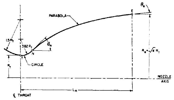 Figure 4-13.-Parabolic approximation of bell nozzle contour.
section with a radius of from the throat to the point N and a parabola from there to the exit E .
For the design of a specific nozzle, the following data are required: (1) Throat diameter, , inches (2) Axial length of the nozzle from throat to exit plane, , inches (or the desired fractional length based on a conical nozzle) (3) Expansion area ratio (4) Initial wall angle of the parabola, , degrees (5) Nozzle exit wall angle, , degrees
The wall angles, and are shown in figure 4-14 as a function of the expansion area ratio .
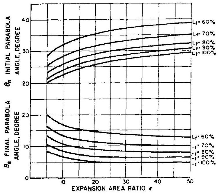 Figure 4-14.- and as function of expansion area ratio .
Optimum nozzle contours can be approximated quite accurately by selecting the proper inputs. Although no allowance is made for different propellant combinations, experience has shown that the effect of specific heat ratio upon the contour is small. A computer program can be readily set up to perform the calculation.
4. Annular Nozzles
Based on the momentum theorem, for ideal expansion the thrust generated by a thrust chamber depends only upon the mass flow conditions (velocity and direction) at the nozzle exit. In some nozzle designs, such as annular nozzles, the gas flow at the throat is not necessarily parallel to the axis, but the exit flow is similar to that of a conical or bell nozzle and thus produces the same thrust results.
There are two basic types of annular nozzles: the radial in-flow type (spike nozzle) and the radial out-flow type (expansion-deflection or E-D; reverse-flow or R-F; and horizontal-flow or H-F nozzles). They are shown in figure 4-15, together with conventional conical and bell noz- zles. For comparison of the effect of nozzle type on size, all nozzles shown are scaled to the same thrust level, nozzle expansion area ratio, and theoretical nozzle efficiency. These nozzles show potential of adapting their geometry to space vehicle application, because shortened nozzles reduce interstage structure weight and will permit an increase in payload through increased performance for a given length.
The nozzle expansion area ratio for an annular nozzle is defined by equation (4-9):
where the projected area of the contoured nozzle wall equals nozzle exit plane area , less the centerbody projected area . Another conveient design parameter for annular nozzles is the annular diamoter ratio, , where is the throat diameter of an equivalent circular throat, and the centerbody diameter. The param.cter is an index of the annular nozzle design
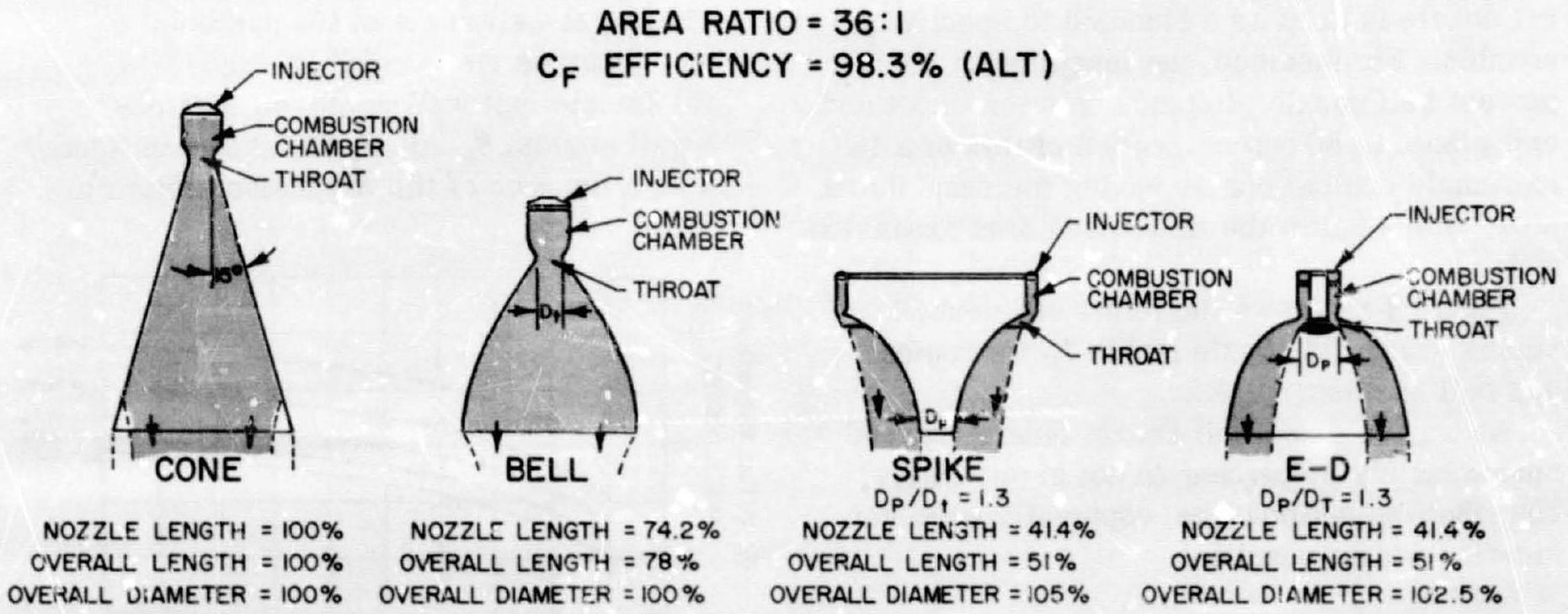
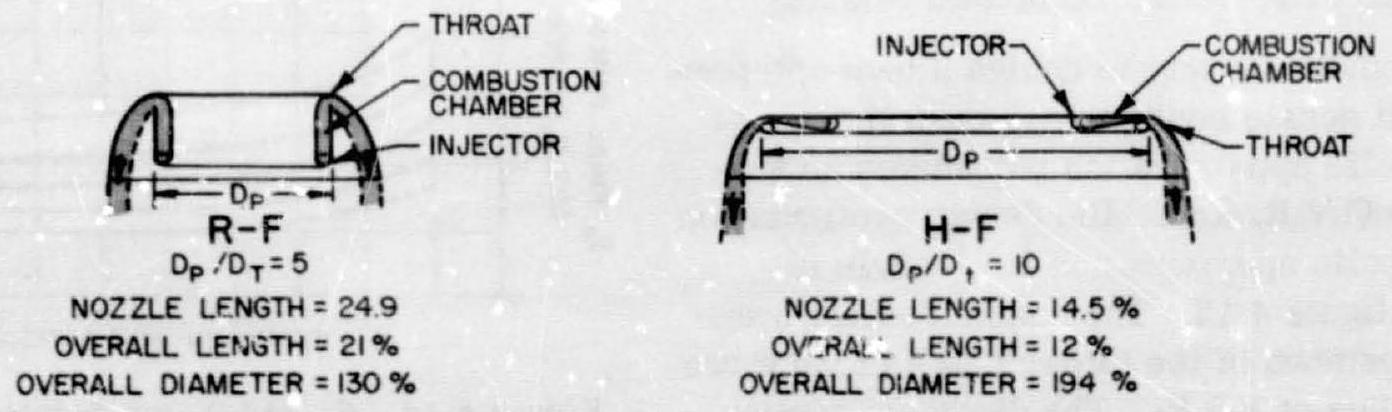 Figure 4-15.-Comparison of nozzle shapes.
geometry as compared to a conventional nozzle. The contour-calculating methods for annular nozzles are similar to those for bell nozzles.
In a conical or bell nozzle, the gases may expand to pressures well below the ambient (sealevel or low-altitude operation) before flow separation from the nozzle wall occurs. As explained in chapter I, for nozzles with large area ratios, this overexpansion results in thrust losses at low altitudes. Annular nozzles, because of their special characteristics, are not subject to these losses. As shown in figure 4-16 for an E-D nozzle (and equally applicable to other annular nozzles), the back pressure at the back face of the centerbody plays an important role in regulating the nozzle flow. The value of is a function of the ambient pressure and generally is lower than ambient. Downstream of the throat, the expansion of the gases around the centerbody shoulder will continue unaffected until this base pressure is reached. After the initial gas expansion through the constant-Mach line CD, the downstream flow of the gases is controlled by the following two boundary conditions: (1) The nozzle wall contour which turns the gases to near-axial flow. (2) The base pressure which influences the free stream surface of the inner jet boundary. Because of the curved-wall contour, the gases are deflected, which leads to some compression and local increases in wall pressure. A typical nozzle wall pressure distribution for low-altitude operation is shown in figure 4-16. This com-
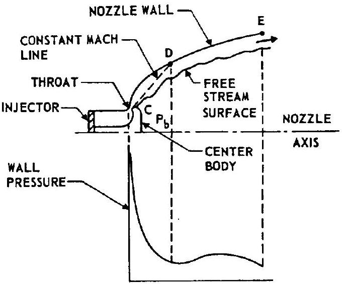 Figure 4-16.-E-D nozzle at low altitude operation.
 Figure 4-17.-E-D nozzle at high altitude operation.
pressive turning at the nozzle wall, which is also typical for the spike nozzle, is responsible for improved nozzle performance at low altitude. Because of the self-adjusting nature of the inner jet boundary, there is no flow separation from the nozzle wall, as is the case for a conventional nozzle.
At high-altitude operation the base pressure becomes so low that the nozzle flow converges behind the centerbody, as shown in figure 4-17. Since the flow at the closure point must be axial, a shock wave may occur depending on the flow conditions. However, the expansion of the gases may continue unaffected up to the end of the nozzle. The nozzle wall pressure distribution under this condition is also shown in figure 4-17.
An improved spike nozzle concept is the aerodynamic spike nozzle. This nozzle concept is a truncated annular spike nozzle (radial inflow type), which utilizes a small amount of secondary flow introduced into the nozzle base region.
Performance of the aerodynamic spike nozzle is a function of various nozzle geometric parameters, the amount of secondary flow, the manner in which this secondary flow is introduced, and the relative energy between the primary and secondary streams. To describe the flow field and interrelated effect of truncating the spike nozzle,
[^2]the base pressure and the base pressure increase achieved through the secondary flow addition requires a lengthy, detailed discussion; only the basic operation can be presented here.
The primary flow (high-pressure gases) which produces the major portion of the engine thrust is exhausted from an annular-type combustion chamber and expands against the metal surface of the center trunated-spike nozzle (fig. 4-18). The characteris of the primary flow field upstream of the base, shown as region 1 in figure 4-18, are determined by the annular throat geometry, the nozzle wall contour, and the ambient pressure. The annular primary flow continues to expand beyond the nozzle surface and encloses a subsonic, recirculating flow field in the base region (region 2). The pressure acting on the nozzle base contributes additional thrust to the nozzle.
When a small amount of secondary flow is introduced into the base (added to the recirculating flow), the base pressure is increased further. As the secondary flow is increased, the overall nozzle efficiency (considering the additional flow) increases because of this increase in base pressure. There is a limit to this gain in efficiency, and an optimum secondary flow exists for each configuration.
The outer surface of the annular primary flow is a free-jet boundary, which is influenced by ambient pressure. This ambient pressure influence on the primary nozzle flow endows this type of nozzle with altitude compensation. In operation at high-pressure ratios (i.e., altitude conditions), the outer free-jet boundary of the primary flow expands outward, governed by the Prandtl-Meyer turning angle at the throat. At low-pressure ratios (i.e., sea level operation). the relatively higher ambient pressure com-
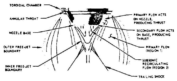 Figure 4-18.-Aerodynamic spike flow field illustrated under altitude conditions.
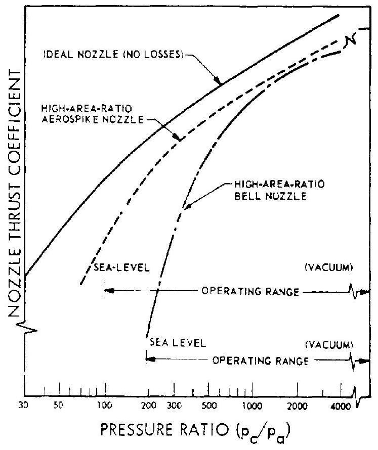 Figure 4-19.-Nozzle performance comparison.
presses the outer free-jet boundary of the primary flow field. This compression increases the static pressure on the nozzle wall and partially offsets the negative effect of the higher ambient pressure on the back side of the nozzle. The base pressure also is increased with the higher ambient, because the compressed primary flow field, which influences the base pressure, has higher static pressures. This combination of flow field effects provides the altitude compensation inherent to the aerodynamic spike nozzle.
Figure presents the performance comparison of various nozzle designs. The nozzle thrust coefficient for an ideal nozzle (i.e., a variable-area-ratio nozzle having the optimum expansion for each chamber pressure to ambient pressure ratio, ) is shown together with those of the high-area-ratio aerodynamic spike and bell nozzle. As is evident, the curve of the aerodynamic spike follows the ideal nozzle performance (altitude-compensation), rather than dropping off rapidly like the bell design at low (i.e., sea level) operating points. All nozzles have a higher at a high (i.e., vacuum).
The development of the annular-nozzle concept may influence the design of rocket vehicles, especially in the areas of boattail structure and mission staging optimization. The advantages and disadvantages of annular nozzles are summarized as follows:
Advantages
(1) Shortened nozzle length for the same performance, or increased performance (higher expansion area ratios) for a given length. (2) Improved performance at sea level or low altitudes. (Annular nozzles with high expansion area ratios can be used for a single-stage sea level to vacuum vehicle mission.) (3) The relatively stagnant region in the center of the nozzle can possibly be used for installation of gas generators, turbopumps, tanks, auxiliary equipment, and turbine gas discharges. (4) A segmented combustion chamber design approach can be used, easing development effort (individual segments can be built and tested during the early phases) and improving combustion stability.
Disadvantages
(1) Relatively high cooling requirements, because of higher heat fluxes and greater surface areas to be cooled. (2) Heavier structural construction in some applications. (3) Manufacturing difficulties.
Sample Calculation (4-2)
Lay out the thrust chamber internal configuration (cylindrical combustion chamber with bell nozzle) for the engines on the Alpha vehicle with the data derived from sample calculation (4-1) and the following required chamber thrusts : (a) A-1 stage engine: at sea level (b) A-2 stage engine: at altitude (c) A-3 stage engine: at altitude (d) A-4 stage engine: at altitude The detailed calculations and their results are presented in the following for the first-stage engine only. For the other stages, the calculation results are summarized in figures 4-21 to
4-23. The reader is urged to conduct his own calculations using the first stage as a guide, and to compare his results with those shown.
Solution
A-1 Stage Engine:
From sample calculation (4-1): Design sea level ;
Substitute into equation (1-33): Throat area: Throat diameter:
Exit diameter:
Use a combustion chamber of 45 in for application. Substitute into equation (4-4):
Chamber volume: in Use a nozzle convergent half angle of , a contraction area ratio , and a circular arc of radius , or 18.68 in, for nozzle contour upstream of the throat.
Chamber diameter: in
Use equation (4-7) to calculate the chamber convergent cone length
Convergent cone length
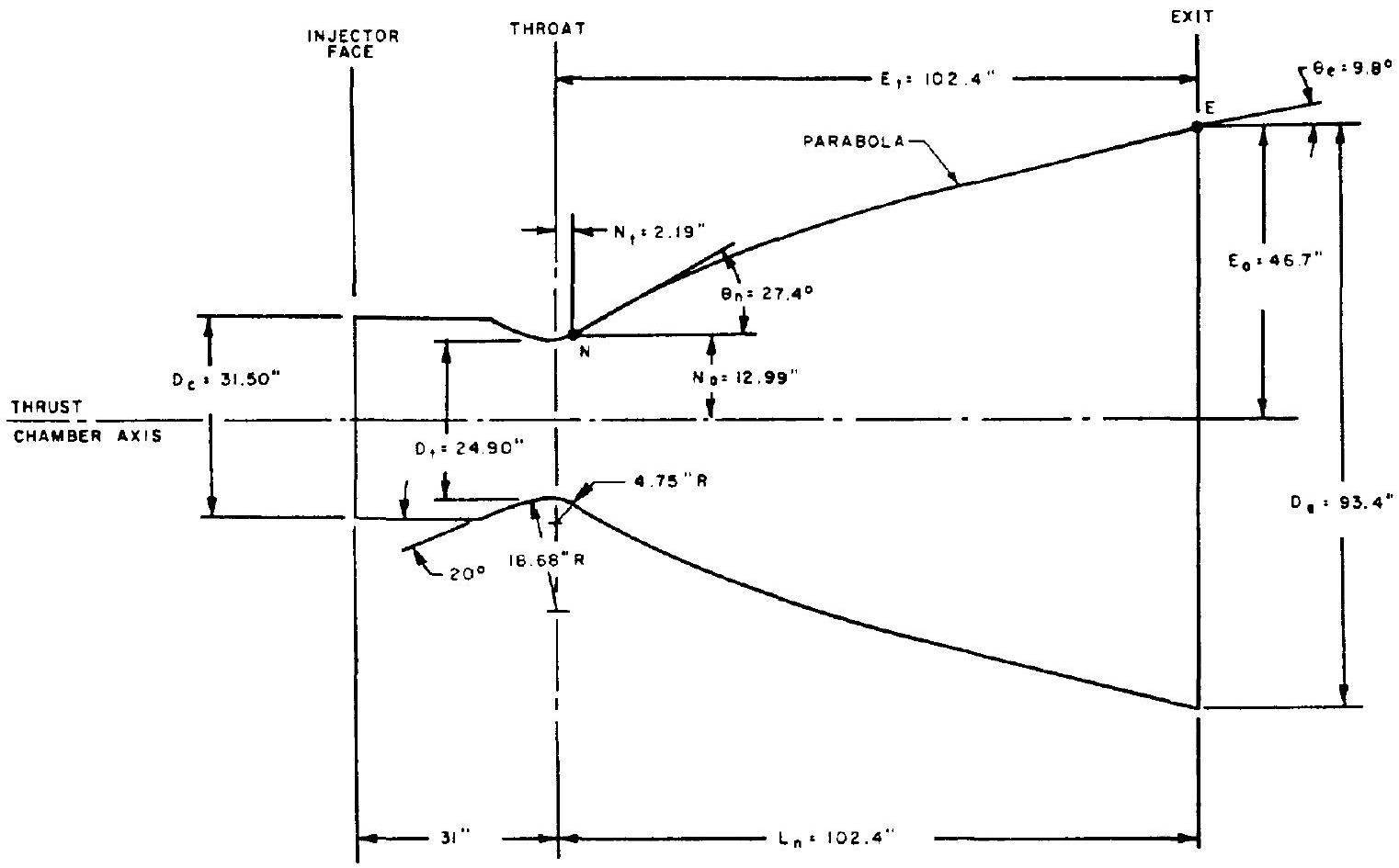 Figure 4-20.-A-1 stage engine thrust chamber internal configuration layout: bell .
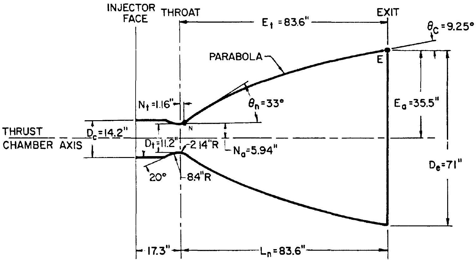 Figure 4-21.-A-2 stage engine thrust chamber, internal configuration layout: bell, .
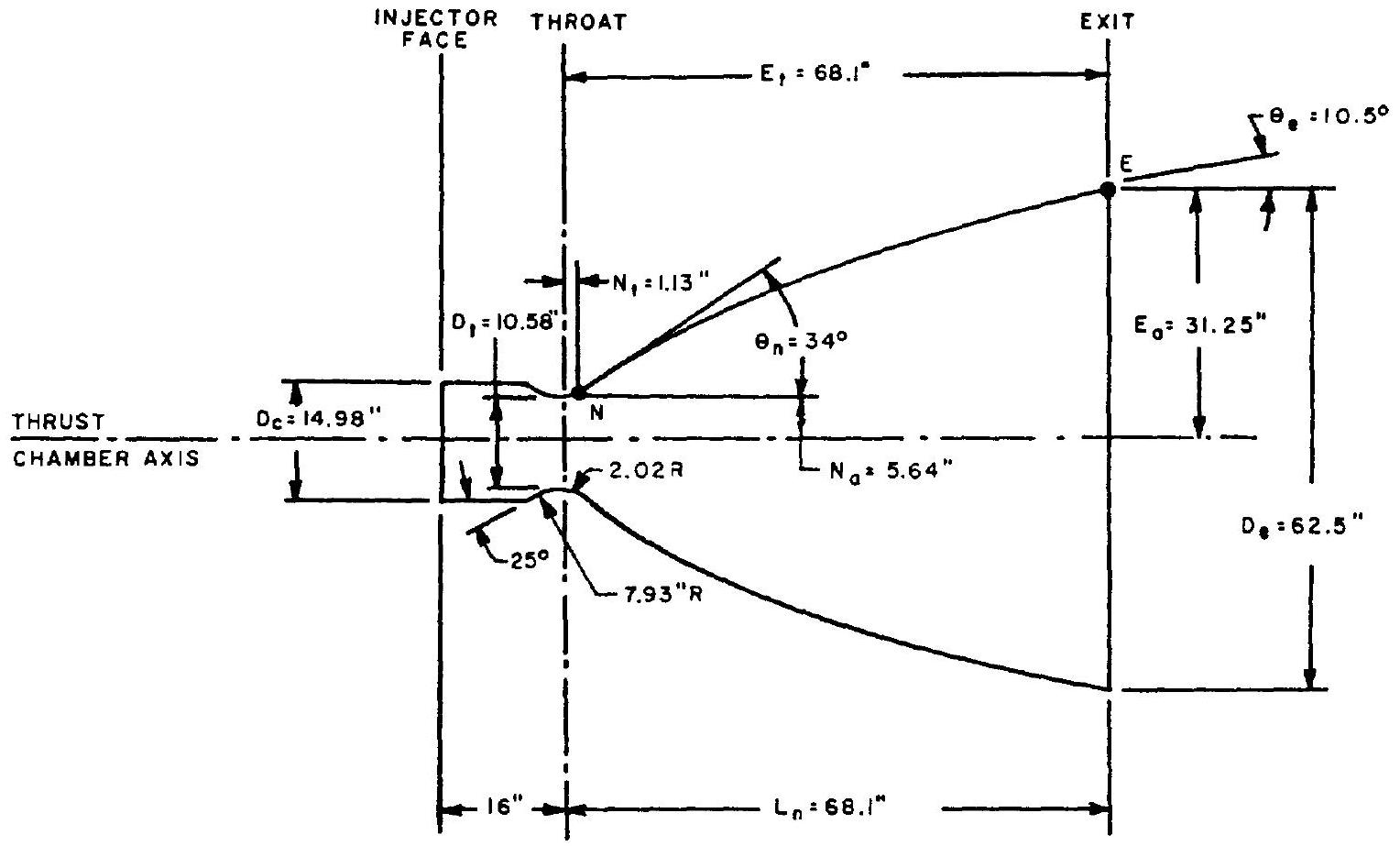 Figure 4-22.-A-3 stage engine thrust chamber, internal configuration layout: bell .
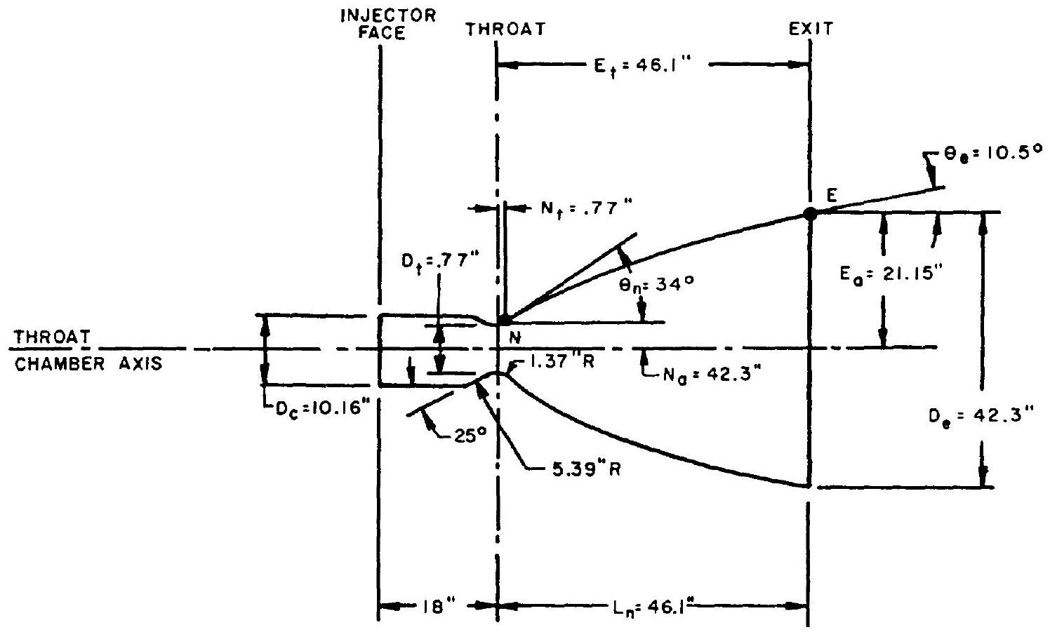 Figure 4-23.-A-4 stage engine thrust chamber, internal configuration layout: bell .
Using the frustrum cone volume equation and neglecting the slight rounding of the throat, the approximate convergent cone volume is obtained:
Required volume for cylindrical chamber section
Required length for cylindrical chamber section
Distance from injector face to throat
Design an " 80 -percent bell" nozzle configuration using the parabolic approximation procedure. The nozzle contour downstream of the throat will be a circular arc of radius , or 4.75 inches. By definition, the nozzle length will be 80 percent of the length for an equivalent half-angle conical nozzle. Substitute into equation (4-7)
The parabolic contour wall angles and can be derived from figure 4-14, for and ; and . The location of N and E along the nozzle contour, with respect to throat and nozzle axis, can be calculated
With the aid of the established coordinates for points N and E , and the angles and , a parabola can be fitted to complete the contour. The general layout of the A-1 stage engine thrust chamber is shown in figure 4-20. With the aid of a computer program, more accurate calculations of the divergent nozzle contour can be made by the method of characteristics.
Since the calculations for the thrust chamber configuration are based on the calculated design value which has to be verified by later actual testing, a slight change of chamber pressure is usually allowed to compensate for deviations in order to meet the required thrust value.